


Challenging Aotearoa NZ to create a building system that delivers better outcomes for all
News
-
ArchEngBuild is back for 2024!
Bringing together 30 architecture, engineering and construction management students, with a prize of $10,000 NZD for the winning team.
View more -
BRANZ latest House Insulation Guide update
It's time to ensure you're using the most up-to-date version!
View more -

2024 industry insights report
A pulse check of the building and construction sector to identify the building system’s needs.
View more
Featured publications
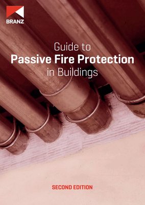
The purpose of the guide is to enable the effective use of passive fire protection including providing the right product and installing it correctly in the right situation. It describes good practice for the specification, approval, installation and verification of passive fire protection. Specific processes may vary between jurisdictions and the professional people involved, but in all cases, the appropriate product must be correctly installed.
This guide introduces the principles of passive fire protection. It identifies the requirements of the New Zealand Building Code (NZBC), explains the terminology commonly used and identifies the main building components that have a passive fire protection role